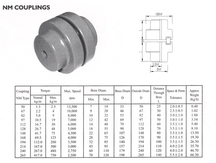
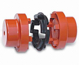
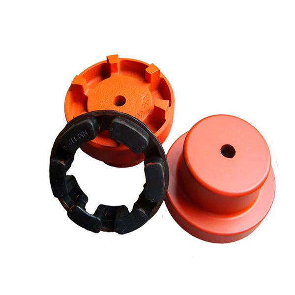
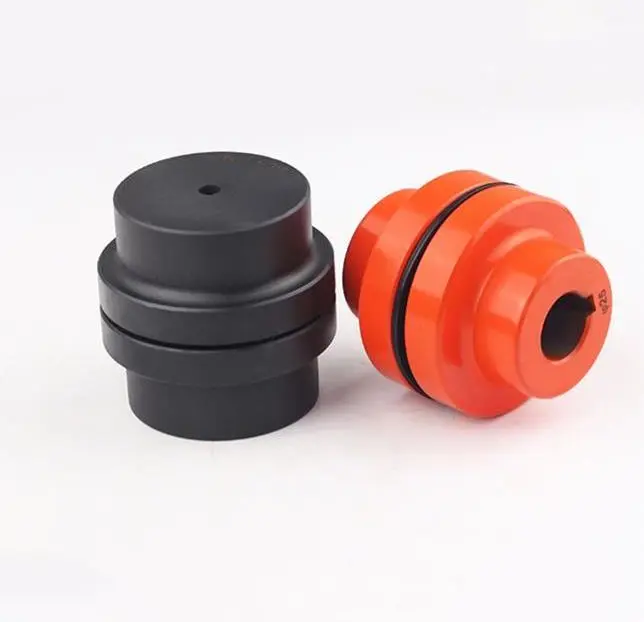
We are the leading top Chinese coupling manufacturer, and are specializing in various high quality NM coupling.
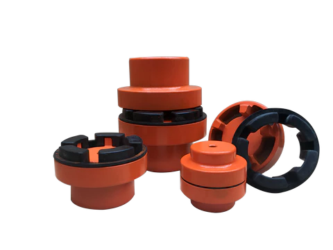
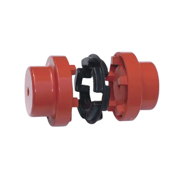
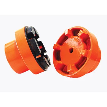
1. Material: Cast iron, Rubber. 2. OEM and ODM are available 3. High efficient in transmission 4. Finishing: Painted. 5. High quality with competitive price 6. Different models suitable for your different demands 7. Stock for different bore size on both sides available. 8. Application in wide range of environment. 9. Quick and easy mounting and disassembly. 10. Resistant to oil and electrical insulation. 11. Identical clockwise and anticlockwise rotational characteristics. 12. Small dimension, low weight, high transmitted torque. 13. It has good performance on compensating the misalignment.
How do flexible couplings compare to other types of couplings in terms of performance?
Flexible couplings offer distinct advantages and disadvantages compared to other types of couplings, making them suitable for specific applications. Here is a comparison of flexible couplings with other commonly used coupling types in terms of performance:
Rigid Couplings:
Rigid couplings are simple in design and provide a solid connection between two shafts, allowing for precise torque transmission. They do not offer any flexibility and are unable to compensate for misalignment. As a result, rigid couplings require accurate shaft alignment during installation, and any misalignment can lead to premature wear and increased stress on connected equipment. Rigid couplings are best suited for applications where shaft alignment is precise, and misalignment is minimal, such as in well-aligned systems with short shaft spans.
Flexible Couplings:
Flexible couplings, as discussed previously, excel at compensating for misalignment between shafts. They offer angular, parallel, and axial misalignment compensation, reducing stress on connected components and ensuring smooth power transmission. Flexible couplings are versatile and can handle various applications, from light-duty to heavy-duty, where misalignment, vibration damping, or shock absorption is a concern. They provide a cost-effective solution for many industrial, automotive, and machinery applications.
Oldham Couplings:
Oldham couplings are effective at compensating for angular misalignment while maintaining constant velocity transmission. They offer low backlash and electrical isolation between shafts, making them suitable for precision motion control and applications where electrical interference must be minimized. However, Oldham couplings have limited capacity to handle parallel or axial misalignment, and they may not be suitable for applications with high torque requirements.
Gear Couplings:
Gear couplings are robust and can handle high torque levels, making them suitable for heavy-duty applications such as mining and steel mills. They offer good misalignment compensation and have a compact design. However, gear couplings are relatively more expensive and complex than some other coupling types, and they may generate more noise during operation.
Disc Couplings:
Disc couplings provide excellent misalignment compensation, including angular, parallel, and axial misalignment. They have high torsional stiffness, making them ideal for applications where accurate torque transmission is critical. Disc couplings offer low inertia and are suitable for high-speed applications. However, they may be more sensitive to shaft misalignment during installation, requiring precise alignment for optimal performance.
Conclusion:
The choice of coupling type depends on the specific requirements of the application. Flexible couplings excel in compensating for misalignment and vibration damping, making them versatile and cost-effective solutions for many applications. However, in situations where high torque, precision, or specific electrical isolation is necessary, other coupling types such as gear couplings, disc couplings, or Oldham couplings may be more suitable. Proper selection, installation, and maintenance of the coupling are essential to ensure optimal performance and reliability in any mechanical system.
Can flexible couplings be used in corrosive or harsh environments?
Yes, flexible couplings can be designed and selected to be used in corrosive or harsh environments. The choice of materials and coatings plays a crucial role in ensuring the coupling’s durability and performance under challenging conditions.
Corrosion-Resistant Materials:
In corrosive environments, it is essential to use materials that can withstand chemical attacks and oxidation. Stainless steel, specifically grades like 316 or 17-4 PH, is commonly chosen for flexible couplings in such situations. Stainless steel offers excellent corrosion resistance, making it suitable for applications where the coupling may come into contact with corrosive substances or moisture.
Special Coatings:
For certain harsh environments, coupling manufacturers may apply special coatings to enhance the coupling’s corrosion resistance. Examples of coatings include zinc plating, nickel plating, or epoxy coatings. These coatings provide an additional layer of protection against corrosive agents and help extend the coupling’s lifespan.
Sealed Designs:
In environments where the coupling is exposed to contaminants like dust, dirt, or moisture, sealed designs are preferred. Sealed flexible couplings prevent these substances from entering the coupling’s internal components, thus reducing the risk of corrosion and wear. The sealed design also helps to maintain the coupling’s performance over time in challenging conditions.
High-Temperature Applications:
For harsh environments with high temperatures, flexible couplings made from high-temperature resistant materials, such as certain heat-resistant stainless steels or superalloys, can be used. These materials retain their mechanical properties and corrosion resistance even at elevated temperatures.
Chemical Resistance:
For applications where the coupling might encounter chemicals or solvents, it is essential to select a coupling material that is chemically resistant. This prevents degradation and ensures the coupling’s integrity in such environments.
Specialized Designs:
In some cases, where the environment is exceptionally harsh or unique, custom-designed flexible couplings may be necessary. Engineering a coupling to meet the specific demands of the environment ensures optimal performance and reliability.
Consultation with Manufacturers:
When considering flexible couplings for corrosive or harsh environments, it is advisable to consult with coupling manufacturers or engineering experts. They can provide valuable insights and recommend suitable materials, coatings, and designs based on the specific operating conditions.
Summary:
Flexible couplings can indeed be used in corrosive or harsh environments, provided the appropriate materials, coatings, and designs are chosen. Stainless steel, sealed designs, and special coatings are some of the solutions that enhance the coupling’s corrosion resistance and performance. It is essential to consider the specific environment and application requirements when selecting a flexible coupling to ensure optimal functionality and durability in challenging conditions.
Are there any limitations or disadvantages of using flexible couplings?
While flexible couplings offer numerous advantages, they do come with some limitations and disadvantages that should be considered when selecting them for specific applications. Here are some of the common limitations and disadvantages of using flexible couplings:
Torsional Stiffness: Flexible couplings provide some level of torsional flexibility, which is advantageous in many applications. However, in systems that require high precision and minimal angular deflection, the inherent flexibility of the coupling may not be suitable. In such cases, a rigid coupling may be more appropriate.
Limitation in High-Torque Applications: While some flexible couplings can handle moderate to high torque levels, they may not be as well-suited for extremely high-torque applications. In such cases, specialized couplings, such as gear couplings, may be required to handle the high torque demands.
Temperature Limitations: The performance of certain flexible coupling materials, especially elastomers and plastics, may be affected by extreme temperature conditions. High temperatures can lead to premature wear and reduced lifespan of the coupling, while low temperatures may result in reduced flexibility and potential brittleness.
Chemical Compatibility: Certain flexible coupling materials may not be compatible with certain chemicals or substances present in the application’s environment. Exposure to chemicals can cause degradation or corrosion of the coupling material, affecting its performance and lifespan.
Installation and Alignment: Flexible couplings require proper installation and alignment to function effectively. If not installed correctly, misalignment issues may persist, leading to premature wear and reduced performance. Aligning the shafts accurately can be time-consuming and may require specialized equipment and expertise.
Cost: In some cases, flexible couplings may be more expensive than rigid couplings due to their more complex design and use of specialized materials. However, the cost difference is often justified by the benefits they offer in terms of misalignment compensation and vibration damping.
Service Life: The service life of a flexible coupling can vary depending on the application’s conditions and the quality of the coupling. Regular maintenance and timely replacement of worn or damaged parts are essential to ensure the coupling’s longevity and prevent unexpected failures.
Despite these limitations, flexible couplings remain highly valuable components in a wide range of applications, providing efficient torque transmission and compensating for misalignment. Proper selection, installation, and maintenance can help mitigate many of the disadvantages associated with flexible couplings, ensuring their reliable and long-lasting performance in various mechanical systems.
We are the leading top Chinese coupling manufacturer, and are specializing in various high quality NM coupling.
1. Material: Cast iron, Rubber. 2. OEM and ODM are available 3. High efficient in transmission 4. Finishing: Painted. 5. High quality with competitive price 6. Different models suitable for your different demands 7. Stock for different bore size on both sides available. 8. Application in wide range of environment. 9. Quick and easy mounting and disassembly. 10. Resistant to oil and electrical insulation. 11. Identical clockwise and anticlockwise rotational characteristics. 12. Small dimension, low weight, high transmitted torque. 13. It has good performance on compensating the misalignment.
Can flexible couplings be used in both horizontal and vertical shaft arrangements?
Yes, flexible couplings can be used in both horizontal and vertical shaft arrangements. The design of flexible couplings allows them to accommodate misalignment and compensate for angular, parallel, and axial displacements between the shafts, making them suitable for various shaft orientations.
Horizontal Shaft Arrangements:
In horizontal shaft arrangements, where the shafts are parallel to the ground or horizontal plane, flexible couplings are commonly used to connect two rotating shafts. These couplings help transmit torque from one shaft to another while accommodating any misalignment that may occur during operation. Horizontal shaft arrangements are common in applications such as pumps, compressors, conveyors, and industrial machinery.
Vertical Shaft Arrangements:
In vertical shaft arrangements, where the shafts are perpendicular to the ground or vertical plane, flexible couplings are also applicable. Vertical shafts often require couplings that can handle the additional weight and forces resulting from gravity. Flexible couplings designed for vertical applications can support the weight of the rotating equipment while allowing for some axial movement to accommodate thermal expansion or other displacements. Vertical shaft arrangements are commonly found in applications such as pumps, gearboxes, turbines, and some marine propulsion systems.
Considerations for Vertical Shaft Arrangements:
When using flexible couplings in vertical shaft arrangements, there are a few additional considerations to keep in mind:
Thrust Load: Vertical shafts can generate thrust loads, especially in upward or downward direction. The flexible coupling should be selected based on its capacity to handle both radial and axial loads to accommodate these forces.
Lubrication: Some vertical couplings may require additional lubrication to ensure smooth operation and reduce wear, particularly if they are exposed to high axial loads or extended vertical shafts.
Support and Bearing: Proper support and bearing arrangements for the vertical shaft are essential to prevent excessive shaft deflection and ensure the flexible coupling functions correctly.
Overall, flexible couplings are versatile and adaptable to various shaft orientations, providing efficient power transmission and misalignment compensation. Whether in horizontal or vertical arrangements, using the appropriate flexible coupling design and considering the specific application requirements will help ensure reliable and efficient operation.
What are the differences between elastomeric and metallic flexible coupling designs?
Elastomeric and metallic flexible couplings are two distinct designs used to transmit torque and accommodate misalignment in mechanical systems. Each type offers unique characteristics and advantages, making them suitable for different applications.
Elastomeric Flexible Couplings:
Elastomeric flexible couplings, also known as flexible or jaw couplings, employ an elastomeric material (rubber or similar) as the flexible element. The elastomer is typically molded between two hubs, and it acts as the connector between the driving and driven shafts. The key differences and characteristics of elastomeric couplings include:
Misalignment Compensation: Elastomeric couplings are designed to handle moderate levels of angular, parallel, and axial misalignment. The elastomeric material flexes to accommodate the misalignment while transmitting torque between the shafts.
Vibration Damping: The elastomeric material in these couplings offers excellent vibration dampening properties, reducing the transmission of vibrations from one shaft to another. This feature helps protect connected equipment from excessive vibrations and enhances system reliability.
Shock Load Absorption: Elastomeric couplings can absorb and dampen shock loads, protecting the system from sudden impacts or overloads.
Cost-Effective: Elastomeric couplings are generally more cost-effective compared to metallic couplings, making them a popular choice for various industrial applications.
Simple Design and Installation: Elastomeric couplings often have a straightforward design, allowing for easy installation and maintenance.
Lower Torque Capacity: These couplings have a lower torque capacity compared to metallic couplings, making them suitable for applications with moderate torque requirements.
Common Applications: Elastomeric couplings are commonly used in pumps, compressors, fans, conveyors, and other applications that require moderate torque transmission and misalignment compensation.
Metallic Flexible Couplings:
Metallic flexible couplings use metal components (such as steel, stainless steel, or aluminum) to connect the driving and driven shafts. The metallic designs can vary significantly depending on the type of metallic coupling, but some general characteristics include:
High Torque Capacity: Metallic couplings have higher torque transmission capabilities compared to elastomeric couplings. They are well-suited for applications requiring high torque handling.
Misalignment Compensation: Depending on the design, some metallic couplings can accommodate minimal misalignment, but they are generally not as flexible as elastomeric couplings in this regard.
Stiffer Construction: Metallic couplings are generally stiffer than elastomeric couplings, offering less vibration dampening but higher torsional stiffness.
Compact Design: Metallic couplings can have a more compact design, making them suitable for applications with limited space.
Higher Precision: Metallic couplings often offer higher precision and concentricity, resulting in better shaft alignment.
Higher Cost: Metallic couplings are typically more expensive than elastomeric couplings due to their construction and higher torque capacity.
Common Applications: Metallic couplings are commonly used in high-speed machinery, precision equipment, robotics, and applications with high torque requirements.
Summary:
In summary, the main differences between elastomeric and metallic flexible coupling designs lie in their flexibility, torque capacity, vibration dampening, cost, and applications. Elastomeric couplings are suitable for applications with moderate torque, misalignment compensation, and vibration dampening requirements. On the other hand, metallic couplings are chosen for applications with higher torque and precision requirements, where flexibility and vibration dampening are less critical.
How do you select the appropriate flexible coupling for a specific application?
Choosing the right flexible coupling for a specific application requires careful consideration of various factors to ensure optimal performance, reliability, and longevity. Here are the key steps to select the appropriate flexible coupling:
Application Requirements: Understand the specific requirements of the application, including torque and speed specifications, misalignment conditions, operating environment (e.g., temperature, humidity, and presence of corrosive substances), and space limitations.
Torque Capacity: Determine the maximum torque that the coupling needs to transmit. Choose a flexible coupling with a torque rating that exceeds the application’s requirements to ensure a safety margin and prevent premature failure.
Misalignment Compensation: Consider the type and magnitude of misalignment that the coupling needs to accommodate. Different coupling designs offer varying degrees of misalignment compensation. Select a coupling that can handle the expected misalignment in the system.
Vibration Damping: If the application involves significant vibrations, choose a flexible coupling with good damping properties to reduce vibration transmission to connected equipment and improve system stability.
Environmental Factors: Take into account the environmental conditions in which the coupling will operate. For harsh environments, consider couplings made from corrosion-resistant materials.
Torsional Stiffness: Depending on the application’s requirements, decide on the desired torsional stiffness of the coupling. Some applications may require high torsional stiffness for precise motion control, while others may benefit from a more flexible coupling for shock absorption.
Cost and Life-Cycle Considerations: Evaluate the overall cost-effectiveness of the coupling over its expected life cycle. Consider factors such as initial cost, maintenance requirements, and potential downtime costs associated with coupling replacement.
Manufacturer Recommendations: Consult coupling manufacturers and their technical specifications to ensure the selected coupling is suitable for the intended application.
Installation and Maintenance: Ensure that the selected flexible coupling is compatible with the equipment and shaft sizes. Follow the manufacturer’s installation guidelines and recommended maintenance practices to maximize the coupling’s performance and longevity.
By following these steps and carefully evaluating the application’s requirements, you can select the most appropriate flexible coupling for your specific needs. The right coupling choice will lead to improved system performance, reduced wear on equipment, and enhanced overall reliability in various mechanical systems and rotating machinery.
GS Spider Coupling for Machine Center Motor XYZ (Red) The elastomer insert is equalizing element of coupling. It transmits torque without backlash or vibration. The elastomer insert defines the characteristics of the entire drive system. Backlash is eliminated by the press fit of the elastomer into the hubs. Through variation of the shore hardness of the elastomer insert, the coupling system can be optimized for the ideal torsional characteristics. GS spider insert for jaw coupling, PU spacer, instead of KTR CZPT elastomer. This GS spider are used for mechanical jaw coupling, as a joint in the transmission shaft. Running quality and service life of the coupling are improved by special pu.. GS Spider Coupling for Machine Center Motor XYZ (Red) Torsion: 22.4~2500NM Wear And Tear: <0.05cm3 / 1.61km Material: Thermally Stable TPU Hardness: Yellow SHA 92, Blue SHA95, Red SHA98 Temperature: -40~100°C Standard: KTR, Germany
Part No.
D (mm)
d (mm)
H (mm)
No. Of Teeth
GS-5
10
—
6
4
GS-7
14
—
8
4
GS-9
20
7
10
4
GS-12
25
8
12
4
GS-14
30
10
12
4
GS-19
40
18
14.5
6
GS-24
54
26
15.2
8
GS-28
65
30
19
8
GS-38
80
38
22
8
GS-42
95
46
24
8
GS-48
104
51
25.5
8
GS-55
120
60
27
8
GS-65
135
68
32
8
GS-75
160
80
37
10
GS Spider Coupling for Machine Center Motor XYZ (Red)
PRODUCT ADVANTAGES
With special secret formula, our coupling spiders can be stably operated for 2~5 years under different working conditions, which is very closed to the KTR’s service life. More Products:
Various types of couplings rubber elastomer models are as follows:
MT rubber coupling (MT1-MT13),
GR rubber coupling (GR10-GR180),
GS rubber coupling (GS7-GS90),
T Hexagon back wheel coupling (hexagonal elasticity pad T70 ~ 210).,
Please inquire us if you need Rubber Coupling Elastomer and other types couplings inserts.
Different Types Of Hydraulic Seals
Application
Type
Material
Rod Seals
UN
TPU(PU,Polyurethane)
UNS
TPU(PU,Polyurethane)
UHS
TPU(PU,Polyurethane)
IDU
TPU(PU,Polyurethane)
U+S
PU+NBR
UPH
NBR & FKM
Step Seal
NBR+PTFE
VES
Rubber+Fabric
IDI
PU
ISI
PU
Piston Seals
SPG
NBR+PTFE
SPGW
NBR+PTFE
SPGO
NBR+PTFE
KDAS
NBR+PU+POM
ODI
PU
OSI
PU
ODU
PU
Dust Wiper Seals
DH/DHS
PU
LBH
NBR & FKM
J/JA
PU
DKB
NBR & FKM +Metal
DKBI
PU+Metal
DSI
PU
Wear Ring
WR
Phenolic Fabric
Xihu (West Lake) Dis. Tape
PTFE
Xihu (West Lake) Dis. Tape
Phenolic Fabric
Buffer Seal
HBY
PU+Nylon
Back-up Ring
O-Ring
NBR & FKM
X-Ring
NBR & FKM
PTFE Washer
PTFE
GS Spider Coupling for Machine Center Motor XYZ (Red)
Different Type Rotary Shaft Oil Seal
Type
Material
Lip
Spring
Feature
TC
NBR & FKM
Double Lips
Single
Metal Coverd Rubber
TB
NBR
Double Lips
Single
Metal Case
TA
NBR
Double Lips
Single
Metal Case
SC
NBR & FKM
Single
Single
Double Metal Shell
SB
NBR
Single
Single
Metal Case
SA
NBR
Single
Single
Double Metal Shell
DC
NBR
Double Lips
Double
Double Springs
VC
NBR & FKM
Single
Without
Metal Coverd Rubber
VB
NBR
Single
Without
Metal Case
TCV
NBR
Double Lips
Single
High Pressure
TCN
NBR
Double Lips
Single
High Pressure
PTFE
PTFE
Single & Double Lips
Without
Stainless steel
HTCL
NBR & FKM
Double Lips
Single
Inside thread L
HTCR
NBR & FKM
Double Lips
Single
Inside thread R
…………………………………………………………………………………………… More types please contact us. Customization is welcome.
Related Products
GS Spider Coupling for Machine Center Motor XYZ (Red) Oil seals serve to prevent the leakage not only of lubricants, but also water, chemicals, and gas from “gaps” in machinery. Oil seals also serve to prevent the intrusion of dust, soil and sand from the outside air.
Company Profile
HangZhou CZPT Sealing Sci-Tech Co., Ltd. is a scientific and technological production enterprise integrating R&D, production and sales. Our production plant covers an area of about 2,000 square CZPT and has 150 employees.
Our Products: O Ring, Oil Seal, Hydraulic & Pneumatic Seal, Custom CZPT Parts
Production Standard: ASTMD2000
Product Application Scope: Engineering machinery, hydraulic pneumatic, petroleum and natural gas, automobile seals, valves and pipelines, electronic home appliances, food grade, electric power, chemical industry, coal mine, metallurgy, engineering shield machine and other industries, supporting domestic automobile and machinery manufacturers.
We had sell to: More than 40 countries including the United States, Germany, Japan, Britain, Italy, Spain, Russia, Canada, Australia, Malaysia, Philippines, Indonesia, Mexico, Brazil, Peru, Chile, Argentina, Israel, Saudi Arabia, Lebanon, Ukraine, Pakistan, Thailand, Vietnam, etc.
Packaging & Shipping
GS Spider Coupling for Machine Center Motor XYZ (Red) Ship by express, by air, by sea at buyer’s option. rubber oil seal tc oil seal rubber seal manufacturer oil seal tc nbr oil seal tc oil seal fkm oil seal china manufacturer oil seal tc oil seal nbr tc oil seal fkm tc oil seal manufacturer
FAQ
Q 1. What’s the payment term? A: We accept T/T 50% deposit and 50% balance against copy of B/L or L/C at sight, West Union,VISA,Paypal is also accepted. rubber oil seal tc oil seal rubber seal manufacturer oil seal tc nbr oil seal tc oil seal fkm oil seal china manufacturer oil seal tc oil seal nbr tc oil seal fkm tc oil seal manufacturer Q 2. What is the normal lead time for product orders? A: Generally it is 1-2 days if the goods are in stock. or it is 5-10 days if the goods are not in stock, it is according to quantity.tc oil seal tc oil seal nbr tc oil seal nbr rubber oil seal fkm oil seal fkm rubber oil seal manufacture china oil seal
tc oil seal tc oil seal nbr tc oil seal nbr rubber oil seal fkm oil seal fkm rubber oil seal manufacture china oil seal manufacture
Q 3. What is your standard packing? A: All the goods will be packed by carton box and loaded with pallets. Special packing method can be accepted when needed.rubber oil seal tc oil seal rubber seal manufacturer oil seal tc nbr oil seal tc oil seal fkm oil seal china manufacturer oil seal tc oil seal nbr tc oil seal fkm tc oil seal manufacturer
Q 4. Could you please tell us the month capacity of your products ? A: It depends on which model, we produce more than 2500 tons rubber materials per month.
tc oil seal tc oil seal nbr tc oil seal nbr rubber oil seal fkm oil seal fkm rubber oil seal manufacture china oil seal manufacture Q 5. what kind of certificates you have ? A1: We have been ISO9001:2008 and ISO14001:2004 certified by SGS since 2015. A2: We have various rubber compounds approved by ROHS and REACH.
tc oil seal tc oil seal nbr tc oil seal nbr rubber oil seal fkm oil seal fkm rubber oil seal manufacture china oil seal manufacture Q6: How to check the quality of the bulk order? A1: We provide preproduction samples before mass production for all customers if needed. A2: We accept third party inspection such as TUV, INTERTEK, BV, etc.
tc oil seal tc oil seal nbr tc oil seal nbr rubber oil seal fkm oil seal fkm rubber oil seal manufacture china oil seal manufacture Q 7: Do you use any international standards for the rubber products? A: Yes, we mainly use ASTM D2000 standard to define the quality of the rubber materials, tolerances as per ISO3302, ISO2768, etc.rubber oil seal tc oil seal rubber seal manufacturer oil seal tc nbr oil seal tc oil seal fkm oil seal china manufacturer oil seal tc oil seal nbr tc oil seal fkm tc oil seal manufacturer
Q8: What materials are available to produce from your side? A: NBR, EPDM, SILICONE, FPM(FKM), NEOPRENE(CR), NR, IIR, SBR, ACM, AEM, Fluorosilicone(FVMQ), FFKM, Liquid Silicone, Sponge, etc. tc oi l seal tc oil seal nbr tc oil seal nbr rubber oil seal fkm oil seal fkm rubber oil seal manufacture china oil seal manufacture
Q9: Do you provide maintenance on tooling? A: We maintain all tooling and will replace as needed.tc oil seal tc oil seal nbr tc oil seal nbr rubber oil seal fkm oil seal fkm rubber oil seal manufacture china oil seal manufacture
Q10: How many empolyees you have? A:We have 150 empolyees at time of December 2571. tc oil seal tc oil seal nbr tc oil seal nbr rubber oil seal fkm oil seal fkm rubber oil seal manufacture china oil seal manufacture
If you have any other question, please don’t hesitate to contact us:
GS Spider Coupling for Machine Center Motor XYZ (Red)
Standard Or Nonstandard:
Standard
Shaft Hole:
as Standard
Torque:
22.4-2500nm
Bore Diameter:
8-220
Speed:
10000r/M
Structure:
Flexible
Samples:
US$ 10/Piece 1 Piece(Min.Order)
|
Request Sample
Customization:
Available
|
Customized Request
Types of Coupling
A coupling is a device used to join two shafts together and transmit power. Its primary function is to join rotating equipment and allows for some end movement and misalignment. This article discusses different types of coupling, including Magnetic coupling and Shaft coupling. This article also includes information on Overload safety mechanical coupling.
Flexible beam coupling
Flexible beam couplings are universal joints that can deal with shafts that are offset or at an angle. They consist of a tube with couplings at both ends and a thin, flexible helix in the middle. This makes them suitable for use in a variety of applications, from motion control in robotics to attaching encoders to shafts. These couplings are made of one-piece materials and are often made of stainless steel or aluminium alloy. However, they can also be made of acetal or titanium. While titanium and acetal are less common materials, they are still suitable for high-torque applications. For more information about beam couplings, contact CZPT Components. Flexible beam couplings come in a variety of types and sizes. W series couplings are good for general purpose applications and are relatively economical. Stainless steel versions have increased torque capacity and torsional stiffness. Flexible beam couplings made of aluminum are ideal for servo and reverse motion. They are also available with metric dimensions. Flexible beam couplings are made of aluminum alloy or stainless steel. Their patented slot pattern provides low bearing load and high torsional rigidity. They have a long operational life. They also require zero maintenance and can handle angular offset. Their advantages outweigh the disadvantages of traditional beam couplings.
Magnetic coupling
Magnetic coupling transfers torque from one shaft to another using a magnetic field. These couplings can be used on various types of machinery. These types of transmissions are very useful in many situations, especially when you need to move large amounts of weight. The magnetic field is also very effective at reducing friction between the two shafts, which can be extremely helpful if you’re moving heavy items or machinery. Different magnetic couplings can transmit forces either linearly or rotated. Different magnetic couplings have different topologies and can be made to transmit force in various geometric configurations. Some of these types of couplings are based on different types of materials. For example, a ceramic magnetic material can be used for applications requiring high temperature resistance. Hybrid couplings are also available. They have a hybrid design, which allows them to operate in either an asynchronous or synchronous mode. Hysterloy is an alloy that is easily magnetized and is used in synchronous couplings. A synchronous magnetic coupling produces a coupled magnetic circuit. Magnetic coupling is a key factor in many physical processes. In a crystal, molecules exhibit different magnetic properties, depending on their atomic configuration. Consequently, different configurations produce different amounts of magnetic coupling. The type of magnetic coupling a molecule exhibits depends on the exchange parameter Kij. This exchange parameter is calculated by using quantum chemical methods. Magnetic couplings are most commonly used in fluid transfer pump applications, where the drive shaft is hermetically separated from the fluid. Magnetic couplings also help prevent the transmission of vibration and axial or radial loads through the drive shaft. Moreover, they don’t require external power sources, since they use permanent magnets.
Shaft coupling
A shaft coupling is a mechanical device that connects two shafts. The coupling is designed to transmit full power from one shaft to the other, while keeping the shafts in perfect alignment. It should also reduce transmission of shock loads. Ideally, the coupling should be easy to connect and maintain alignment. It should also be free of projecting parts. The shaft couplings that are used in machines are typically made of two types: universal coupling and CZPT coupling. CZPT couplings are designed to correct for lateral misalignment and are composed of two flanges with tongues and slots. They are usually fitted with pins. The T1 tongue is fitted into flange A, while the T2 tongue fits into flange B. Another type of shaft coupling is known as a “sliced” coupling. This type of coupling compensates for inevitable shaft misalignments and provides high torque. Machined slits in the coupling’s outer shell help it achieve high torsional stiffness and excellent flexibility. The design allows for varying engagement angles, making it ideal for many different applications. A shaft coupling is an important component of any machine. Proper alignment of the two shafts is vital to avoid machine breakdowns. If the shafts are misaligned, extra force can be placed on other parts of the machine, causing vibration, noise, and damage to the components. A good coupling should be easy to connect and should ensure precise alignment of the shaft. Ideally, it should also have no projecting parts. Shaft couplings are designed to tolerate a certain amount of backlash, but it must be within a system’s threshold. Any angular movement of the shaft beyond this angle is considered excessive backlash. Excessive backlash results in excessive wear, stress, and breakage, and may also cause inaccurate alignment readings. It is therefore imperative to reduce backlash before the shaft alignment process.
Overload safety mechanical coupling
Overload safety mechanical couplings are devices that automatically disengage when the torque applied to them exceeds a specified limit. They are an efficient way to protect machinery and reduce the downtime associated with repairing damaged machinery. The advantage of overload couplings is their fast reaction time and ease of installation. Overload safety mechanical couplings can be used in a wide range of applications. Their automatic coupling mechanisms can be used on any face or edge. In addition, they can be genderless, incorporating both male and female coupling features into a single mechanism. This means that they are both safe and gender-neutral. Overload safety couplings protect rotating power transmission components from overloads. Overload protection devices are installed on electric motors to cut off power if the current exceeds a certain limit. Likewise, fluid couplings in conveyors are equipped with melting plug elements that allow the fluid to escape when the system becomes too hot. Mechanical force transmission devices, such as shear bolts, are designed with overload protection in mind. A common design of an overload safety mechanical coupling consists of two or more arms and hubs separated by a plastic spider. Each coupling body has a set torque threshold. Exceeding this threshold may damage the spider or damage the jaws. In addition, the spider tends to dampen vibration and absorb axial extension. This coupling style is nearly backlash free, electrically isolating, and can tolerate very little parallel misalignment. A mechanical coupling may also be a universal joint or jaw-clutch coupling. Its basic function is to connect the driver and driven shafts, and limits torque transfer. These devices are typically used in heavy-duty industries, such as steel plants and rolling mills. They also work well with industrial conveyor systems.
CZPT Pulley
The CZPT Pulley coupling family offers a comprehensive range of couplings for motors of all types. Not only does this range include standard motor couplings, but also servo couplings, which require ultra-precise control. CZPT Pulley couplings are also suitable for engine applications where high shocks and vibrations are encountered. CZPT Pulley couplings have a “sliced” body structure, which allows for excellent torsional stiffness and strength. They are corrosion-resistant and can withstand high rotational speeds. The couplings’ design also ensures accurate shaft rotation while limiting shaft misalignment. CZPT Pulley has introduced the CPU Pin Type couplings, which are effective at damping vibration and maintain zero backlash. They are also made from aluminum and are capable of absorbing heat. They come with recessed tightening screws. They can handle speeds up to 4,000 RPM, and are RoHS-compliant. editor by CX 2023-05-18
We are ZheJiang technology joint venture factory in China, professional manufacturer linear guide to global market with good quality and reasonable price. And our linear guide with ISO9001 & ISO14001 approved.
Our new factory around 45000 square meter put into production in 2015. Mainly products CZPT brand linear guide is interworking with CZPT linear guide,ball screw parameter same as TBI ballscrew. We already export our products to some market such as USA,Europe, East Korea,South America, North America,Southeast Asia,Indian,etc.
FAQ
Standard Or Nonstandard:
Standard
Torque:
>80N.M
Structure:
Rigid
Material:
Aluminum
Type:
Bellows Coupling
Transport Package:
Plastic Bag, Cartons, Plywood Boxes
Samples:
US$ 1/Piece 1 Piece(Min.Order)
|
Request Sample
Customization:
Available
|
Customized Request
Types of Couplings
A coupling is a device that connects two shafts together. It transmits power from one end to another and is used for joining rotating equipment. A coupling is flexible and can accommodate a certain amount of end movement and misalignment. This allows for more flexibility in applications. Various types of couplings are available, and each one serves a specific purpose.
Shaft couplings
There are many types of shaft couplings, and they are used in a wide range of applications. The type you need depends on the torque, speed, and horsepower you need, as well as the size of the shaft and its spatial limitations. You may also need to consider whether the coupling will accommodate misalignment. Some shaft couplings are flexible, while others are rigid. Flexible couplings can accommodate up to two degrees of misalignment. They are available in different materials, including aluminum, stainless steel, and titanium. They can also be known by different names, depending on the industry. Some couplings can also be used in a single or multiple-shaft application. The first type of shaft coupling is a rigid coupling, which consists of two parts that fit together tightly around the shafts. These couplings are designed to have more flexibility than sleeved models, and they can be used on fixed shafts as well. The flanged coupling, on the other hand, is designed for heavy loads and is made of two perpendicular flanges. The flanges are large enough to accommodate screws and are generally used with heavy-duty applications. CZPT shaft couplings are a great choice if you’re looking for a shaft coupling that delivers high performance, durability, and low cost. These metal disc-style couplings provide low backlash and high torsional stiffness. Their high misalignment tolerance reduces reaction loads on connected components, which makes them ideal for high-speed precision applications. Available in single and double-disc models, they have torque ratings of up to 2,200 in-lbs. (250N) and are available in fourteen sizes. When using shaft couplings, it is important to choose the right type for your application. Backlash can cause a shaft coupling to break or become unusable. In order to prevent this from happening, you should replace worn or loose parts, and ensure that the hub and key are evenly positioned with the shaft. If you’re using a shaft coupling in a motion-control system, it is important to keep the torque level consistent.
Flexible couplings
Flexible couplings are a type of coupling used to connect two shafts. They are made of rubber or plastic and allow for axial movement of the connected equipment. They do not require lubrication and are resistant to fatigue failure. Flexible couplings are useful for a number of applications. A common type of flexible coupling is the gear coupling, which has gear teeth inside its sleeve. Another type of flexible coupling is the metallic membrane coupling. A metallic membrane coupling is flexible due to flexing metallic discs. One major disadvantage of flexible couplings is their inability to fit certain types of pipe. This is because most couplings need to be stretched to fit the pipe. This problem is often the result of a change in pipe technology. Traditionally, drain and soil pipe is made of ductile iron or cast iron. Today, most pipes are made of PVC, which has a larger outside diameter than either cast or ductile iron. Because of these changes in pipe technology, many coupling manufacturers have not updated their mold sizing. Flexible couplings can be either metallic, elastomeric, or a combination of the three. While there are some common characteristics of each type, you should always consider the tradeoffs of each type before choosing one. Generally, the most important considerations when selecting a flexible coupling are torque, misalignment, and ease of assembly and maintenance. Flexible couplings are used in a wide range of industries. They are useful for connecting two pipes to ensure torque transfer. Although the types available are different, these are the most adaptable couplings in the market. They can withstand movement, vibration, and bending without causing any damage to the piping.
Clutch couplings
A clutch coupling connects two rotating shafts by friction. The clutch engages power when the engine is running, disengaging power when the brake is applied. Clutch couplings are used in applications where the speed of a machine is variable or where continuous service is required. The clutch can transmit power, torque, and axial force. Clutch couplings come in a variety of styles and configurations. Some couplings are flexible, while others are rigid. Flexible couplings are available in a variety of materials, including stainless steel and aluminum. Some couplings also have a non-backlash design, which helps compensate for misalignment. Clutch couplings may be synchronous or asynchronous. Synchronous couplings engage and disengage automatically when the driven machine exceeds its output speed. These couplings are synchronized by a synchronizing mechanism. When the output speed is exceeded, the synchronizing mechanism initiates the engagement process. The synchronizing mechanism does not engage or disengage when the output speed drops. High speed clutches are available from a variety of manufacturers. Some manufacturers offer OEM assembly, repair services, and third-party logistics. These manufacturers serve the automotive, chemical, food, and wood industries, as well as the oilfield and material handling industries. Custom clutches can be manufactured for specific applications and can be fitted with additional features, such as precision machined teeth or keyway slots and grooves. Couplings are available in PCE, C/T, and metric bores. Typically, the size of the input and output shafts will determine which type of coupling is needed. In addition, clutches may be configured for intermediate or high speeds, depending on the required torque.
Clamped couplings
Clamped couplings are commonly used in a variety of industries. They can be used in medical equipment, dental equipment, military equipment, laboratory equipment, and in precision industrial controls. They are available in a wide variety of sizes and keyways. This type of coupling offers a number of advantages, including ease of installation and quick and easy replacement. A clamp coupling connects two parts by compressing them together. The clamping elements can be formed in a variety of ways, but they all have a gap between their surfaces. This friction squeezes the two parts together, much like pulling two rubber gloves apart. This type of coupling is also useful for joining two hoses or piping units. Clamped couplings are designed with a single or double clamping shaft. The clamping parts are mounted in two halves and are held together by eight socket head cap screws. They offer high torque capacity and require little installation space. Their high rigidity ensures good positioning accuracy, making them ideal for dynamic drives. In addition, they are wear-free and offer simple radial assembly. The invention relates to a method and system for clamping pipes to a tank vessel. This invention also relates to a method of loading and unloading tank vessels. The method can be used in oil production platforms and other platforms. A single point mooring method is also used in oil production platforms. Clamped couplings can also be flexible. They can join two shafts together while allowing a small amount of end movement and misalignment. These couplings may also be used in the assembly of motors and gearboxes.
CZPT’s coupling
CZPT couplings are designed to be flexible, allowing them to accommodate misaligned shafts and transmit torque in either direction. They are made with three discs, two hubs, and a center that are arranged with grooves and fins. These features allow for two degrees of freedom during assembly, and can accommodate misalignment of up to 5% of the shaft diameter. CZPT couplings have many uses. For example, they can be used to join two parallel coaxial rotating shafts. Their ability to transmit torque at the same rotation mechanism and speed makes them ideal for applications where electrical currents may be a problem. Because the couplings are not made of metal, they are electrically isolated. Designers should test their couplings during the prototype stage to ensure they are working properly. The CZPT coupling consists of two hubs with one slot on each. An intermediate disk is located between the two hubs. The discs are used to reduce or prevent wear on other machine parts. CZPT couplings are inexpensive and easy to replace. They also have electrical insulation, which makes them easy to repair or replace. CZPT couplings are a popular choice for stepper motor-driven positioning stages. The plastic center disc offers electrical isolation and absorbs shocks from frequent start/stops. These couplings are available in through-hub and blind-bore styles and can be installed in many applications. CZPT couplings also allow for small degrees of shaft misalignment. This allows them to function in systems where shaft access is limited. They are easily removed without tools. editor by CX 2023-04-23
A splined shaft is a machine component with internal and external splines. The splines are formed in four different ways: Involute, Parallel, Serrated, and Ball. You can learn more about each type of spline in this article. When choosing a splined shaft, be sure to choose the right one for your application. Read on to learn about the different types of splines and how they affect the shaft’s performance.
Involute splines
Involute splines in a splined shaft are used to secure and extend mechanical assemblies. They are smooth, inwardly curving grooves that resist separation during operation. A shaft with involute splines is often longer than the shaft itself. This feature allows for more axial movement. This is beneficial for many applications, especially in a gearbox. The involute spline is a shaped spline, similar to a parallel spline. It is angled and consists of teeth that create a spiral pattern that enables linear and rotatory motion. It is distinguished from other splines by the serrations on its flanks. It also has a flat top. It is a good option for couplers and other applications where angular movement is necessary. Involute splines are also called involute teeth because of their shape. They are flat on the top and curved on the sides. These teeth can be either internal or external. As a result, involute splines provide greater surface contact, which helps reduce stress and fatigue. Regardless of the shape, involute splines are generally easy to machine and fit. Involute splines are a type of splines that are used in splined shafts. These splines have different names, depending on their diameters. An example set of designations is for a 32-tooth male spline, a 2,500-tooth module, and a 30 degree pressure angle. An example of a female spline, a fillet root spline, is used to describe the diameter of the splined shaft. The effective tooth thickness of splines is dependent on the number of keyways and the type of spline. Involute splines in splined shafts should be designed to engage 25 to 50 percent of the spline teeth during the coupling. Involute splines should be able to withstand the load without cracking.
Parallel splines
Parallel splines are formed on a splined shaft by putting one or more teeth into another. The male spline is positioned at the center of the female spline. The teeth of the male spline are also parallel to the shaft axis, but a common misalignment causes the splines to roll and tilt. This is common in many industrial applications, and there are a number of ways to improve the performance of splines. Typically, parallel splines are used to reduce friction in a rotating part. The splines on a splined shaft are narrower on the end face than the interior, which makes them more prone to wear. This type of spline is used in a variety of industries, such as machinery, and it also allows for greater efficiency when transmitting torque. Involute splines on a splined shaft are the most common. They have equally spaced teeth, and are therefore less likely to crack due to fatigue. They also tend to be easy to cut and fit. However, they are not the best type of spline. It is important to understand the difference between parallel and involute splines before deciding on which spline to use. The difference between splined and involute splines is the size of the grooves. Involute splines are generally larger than parallel splines. These types of splines provide more torque to the gear teeth and reduce stress during operation. They are also more durable and have a longer life span. And because they are used on farm machinery, they are essential in this type of application.
Serrated splines
A Serrated Splined Shaft has several advantages. This type of shaft is highly adjustable. Its large number of teeth allows large torques, and its shorter tooth width allows for greater adjustment. These features make this type of shaft an ideal choice for applications where accuracy is critical. Listed below are some of the benefits of this type of shaft. These benefits are just a few of the advantages. Learn more about this type of shaft. The process of hobbing is inexpensive and highly accurate. It is useful for external spline shafts, but is not suitable for internal splines. This type of process forms synchronized shapes on the shaft, reducing the manufacturing cycle and stabilizing the relative phase between spline and thread. It uses a grinding wheel to shape the shaft. CZPT Manufacturing has a large inventory of Serrated Splined Shafts. The teeth of a Serrated Splined Shaft are designed to engage with the hub over the entire circumference of the shaft. The teeth of the shaft are spaced uniformly around the spline, creating a multiple-tooth point of contact over the entire length of the shaft. The results of these analyses are usually satisfactory. But there are some limitations. To begin with, the splines of the Serrated Splined Shaft should be chosen carefully. If the application requires large-scale analysis, it may be necessary to modify the design. The splines of the Serrated Splined Shaft are also used for other purposes. They can be used to transmit torque to another device. They also act as an anti-rotational device and function as a linear guide. Both the design and the type of splines determine the function of the Splined Shaft. In the automobile industry, they are used in vehicles, aerospace, earth-moving machinery, and many other industries.
Ball splines
The invention relates to a ball-spinned shaft. The shaft comprises a plurality of balls that are arranged in a series and are operatively coupled to a load path section. The balls are capable of rolling endlessly along the path. This invention also relates to a ball bearing. Here, a ball bearing is one of the many types of gears. The following discussion describes the features of a ball bearing. A ball-splined shaft assembly comprises a shaft with at least one ball-spline groove and a plurality of circumferential step grooves. The shaft is held in a first holding means that extends longitudinally and is rotatably held by a second holding means. Both the shaft and the first holding means are driven relative to one another by a first driving means. It is possible to manufacture a ball-splined shaft in a variety of ways. A ball-splined shaft features a nut with recirculating balls. The ball-splined nut rides in these grooves to provide linear motion while preventing rotation. A splined shaft with a nut that has recirculating balls can also provide rotary motion. A ball splined shaft also has higher load capacities than a ball bushing. For these reasons, ball splines are an excellent choice for many applications. In this invention, a pair of ball-spinned shafts are housed in a box under a carrier device 40. Each of the two shafts extends along a longitudinal line of arm 50. One end of each shaft is supported rotatably by a slide block 56. The slide block also has a support arm 58 that supports the center arm 50 in a cantilever fashion.
Sector no-go gage
A no-go gauge is a tool that checks the splined shaft for oversize. It is an effective way to determine the oversize condition of a splined shaft without removing the shaft. It measures external splines and serrations. The no-go gage is available in sizes ranging from 19mm to 130mm with a 25mm profile length. The sector no-go gage has two groups of diametrally opposed teeth. The space between them is manufactured to a maximum space width and the tooth thickness must be within a predetermined tolerance. This gage would be out of tolerance if the splines were measured with a pin. The dimensions of this splined shaft can be found in the respective ANSI or DIN standards. The go-no-go gage is useful for final inspection of thread pitch diameter. It is also useful for splined shafts and threaded nuts. The thread of a screw must match the contour of the go-no-go gage head to avoid a no-go condition. There is no substitute for a quality machine. It is an essential tool for any splined shaft and fastener manufacturer. The NO-GO gage can detect changes in tooth thickness. It can be calibrated under ISO17025 standards and has many advantages over a non-go gage. It also gives a visual reference of the thickness of a splined shaft. When the teeth match, the shaft is considered ready for installation. It is a critical process. In some cases, it is impossible to determine the precise length of the shaft spline. The 45-degree pressure angle is most commonly used for axles and torque-delivering members. This pressure angle is the most economical in terms of tool life, but the splines will not roll neatly like a 30 degree angle. The 45-degree spline is more likely to fall off larger than the other two. Oftentimes, it will also have a crowned look. The 37.5 degree pressure angle is a compromise between the other two pressure angles. It is often used when the splined shaft material is harder than usual.