The most important perform of an China agricultural gearbox exporter gearbox is to modify the tempo and torque of the energy transmitted from the input provide, this variety of as a tractor’s electrical electrical power get-off (PTO) or motor, to the output shaft that drives the have out or attachment. It will enable farmers to adapt the electrical electricity and tempo specs to match the particular endeavor at hand, these as plowing, China agricultural gearbox exporter tilling, mowing, or harvesting.
one. Oil Stains or Puddles: Search for obvious oil stains or puddles about the gearbox housing or on the floor beneath the equipment. Leaking lubricant can accumulate and kind obvious oil stains, indicating a likely leakage place.
These gearboxes frequently contain a assortment of gears, these as spur gears, helical gears, bevel gears, or worm gears, based on the great speed reduction or enhance and torque multiplication demands. The products ratios and configurations in the gearbox choose the output tempo and torque sent to the utilize.
four. Working Situations: The functioning ailments of the agricultural products can impression the lubricant amount. Gearboxes running in demanding or harsh conditions, this sort of as superior temperatures, large loads, or dusty environments, may involve a lot more recurrent checks to be certain the lubricant stage remains in just the suggested array.
Don’t forget, it is not only essential to test the lubricant level but also to make sure that the proper type of lubricant is employed as advised by the manufacturer. The lubricant type and technical specs can noticeably affect the gearbox’s functionality and lifespan.
3. Frequent Visible Checks: Accomplish visible inspections of the gearbox periodically to verify for any signals of leakage, these types of as oil stains or damp spots all around seals or connections. If there are indications of leakage, immediate focus is needed to identify and rectify the concern.
8. Find Expert Assistance: If you have followed the methods above and however can not decide the resource of the leakage or if the maintenance is further than your knowledge, it is recommended to find aid from a expert technician or get hold of the gearbox manufacturer. They can deliver specialized awareness and machines to diagnose and handle the leakage difficulty properly.
2. Visible Inspection: Carry out a visible inspection of the gearbox, spending close notice to seals, gaskets, fittings, and connections. Look for indications of oil stains, soaked or oily surfaces, or amassed lubricant about these locations. Use a flashlight or other lights applications to boost visibility, in particular in tough-to-attain locations.
4. Examine Seals and Gaskets: Inspect the seals and gaskets completely, as they are popular points of leakage in gearboxes. Seem for symptoms of injury, cracks, have on, or incorrect sealing. Shell out near awareness to input/output shaft seals, cover seals, and any other seals current in the gearbox.
2. First Inspection: When a new gearbox is set up or all through schedule maintenance, it is necessary to examine and affirm the preliminary lubricant stage. This establishes a baseline and ensures that the gearbox is crammed to the suitable amount in advance of operation.
1. Manufacturer’s Recommendations: Always refer to the gearbox manufacturer’s documentation, this kind of as the user guide or routine maintenance guide, for their specific recommendations about lubricant amount checks. They may well give specific time intervals or running hour intervals for examining and replenishing the lubricant.
5. Amplified Temperature: Leakage in gearboxes can result in friction and deficiency of appropriate lubrication, resulting in improved running temperatures. If you detect that the gearbox is running hotter than standard, it could be a indicator of a leakage challenge.
8. Reduced Gearbox Functionality: If you recognize a lower in the efficiency or performance of your agricultural machines, it could be because of to lubricant leakage in the gearbox. Reduced efficiency, these types of as slower procedure, decreased electricity shipping and delivery, or trouble in shifting gears, might show a leakage-related situation.
six. Use Leak Detection Fluids: If the leakage source is not immediately evident, you can use leak detection fluids or dyes. Use the fluid to suspected places, and then use a UV light-weight to examine the gearbox. The fluid will fluoresce under UV mild, producing it simpler to detect the specific area of the leak.
four. Extreme Construct-up of Dust or Dust: Leaking lubricant can attract filth and dust, triggering an too much develop-up in certain areas all over the gearbox. Seem for areas in which grime or dust has amassed extra than typical, as it may perhaps be an indicator of a leakage level.
seven. Contaminated Environment: Leaking lubricant can entice dust, dust, and particles, top to a buildup of contaminants all around the gearbox. Test for too much accumulation of grime or debris that may possibly be adhering to leaked lubricant.
Agricultural pieces refer to the several factors and equipment applied in the agricultural market to boost productivity, performance, and safety in farming operations. These components are created to be made use of in conjunction with China agricultural parts equipment and products to perform precise duties related to planting, cultivating, harvesting, and retaining crops and livestock. Listed here are some common examples of agricultural areas:
one. Tractor Components: Tractors are the workhorses of agriculture, and China agricultural parts their sections involve engines, transmissions, hydraulic systems, fuel units, electrical elements, tires, and a variety of attachments these types of as loaders, plows, and mowers.
2. Harvesting Parts: Harvesting products, these kinds of as mix harvesters, necessitates pieces like cutting blades, sieves, China agricultural parts concaves, belts, chains, augers, and grain bins to successfully acquire and procedure crops like grains, corn, and soybeans.
3. Planting Parts: Planting machinery, this kind of as seeders and planters, make use of parts like seed meters, seed tubes, seed plates, planter discs, depth wheels, and closing wheels to precisely and evenly sow seeds into the soil.
four. Sprayer Pieces: Sprayers used for implementing fertilizers, herbicides, and pesticides demand pieces like nozzles, booms, pumps, valves, filters, hoses, and tanks to be certain specific and helpful application.
5. Irrigation Sections: Irrigation systems, such as sprinklers, drip devices, and pivot systems, use areas like pipes, valves, fittings, filters, emitters, controllers, and sensors to proficiently provide h2o to crops.
6. Livestock Equipment Components: Agricultural components also incorporate components for livestock tools, this sort of as feeding devices, watering units, milking devices, ventilation systems, and fencing materials.
7. Tillage Elements: Tillage tools, this kind of as plows, cultivators, and harrows, count on elements like blades, tines, shanks, sweeps, and rollers to get ready the soil, command weeds, and incorporate crop residue.
8. Hay and Forage Elements: Equipment used for baling, mowing, tedding, raking, and managing hay and forage crops involve elements this kind of as baler twine, belts, blades, teeth, tines, and rollers.
9. Grain Dealing with Components: Grain dealing with products, including grain augers, conveyors, and elevators, have to have areas like belts, pulleys, bearings, flighting, spouts, and sensors to effectively transport and keep harvested grains.
10. Electric power Transmission Areas: Agricultural equipment depends on power transmission elements like belts, chains, gears, sprockets, and bearings to transfer electricity from the motor to a variety of factors and allow their operation.
These are just a several illustrations of the wide vary of agricultural areas accessible. The agricultural marketplace is hugely mechanized and relies on these areas to optimize productiveness, cut down labor, and attain superior outcomes in farming functions.
Cleansing aluminum outdoor household furniture is a clear-cut method. Observe these measures to correctly thoroughly clean your aluminum home furnishings:
one. Assemble Supplies: You are going to will need the adhering to supplies:
2. Remove Loose Particles: Begin by eradicating any unfastened debris, leaves, or grime from the home furnishings. Use a brush or a dry fabric to wipe away the larger sized particles.
3. Put together Cleaning Answer: Fill a bucket with warm h2o and increase a small amount of gentle dish soap or detergent. Blend the option until it sorts a soapy mixture.
four. Clean the Home furniture: Dip a gentle sponge or fabric into the soapy resolution and carefully scrub the aluminum surfaces. Pay back consideration to any locations with grime, stains, or grime. If there are tough-to-arrive at places or intricate models, use a smooth-bristle brush or a toothbrush to clean them carefully. Steer clear of applying abrasive components that can scratch or harm the China aluminum furniture.
5. Rinse with Water: Following scrubbing, rinse the household furniture carefully with thoroughly clean water. You can use a backyard hose or a bucket of h2o to rinse off the soapy residue. Guarantee that all cleaning soap is eliminated to stop any residue or streaks.
6. Dry the Furnishings: Use a clean up fabric or let the furnishings to air dry totally. Make guaranteed there is no standing drinking water still left on the aluminum surface area to reduce drinking water spots or mineral deposits.
7. Utilize Protective Coating (Optional): To greatly enhance the longevity of your aluminum furniture and protect it from the features, you can use a protective coating. There are distinct aluminum home furniture waxes or polishes accessible that can supply an added layer of protection. Stick to the manufacturer’s directions for the selected item.
Frequent cleaning of your aluminum outdoor household furniture will assistance maintain its appearance and lengthen its lifespan. Intention to clean up your household furniture at the very least once or 2 times a 12 months, or as desired, depending on the amount of dust or exposure to the features.
Repacking a hydraulic cylinder consists of replacing the seals and components that help hold the hydraulic fluid in the cylinder. This is a essential guideline on how to repack a hydraulic cylinder:
just one. Scheduling: Assurance that the hydraulic strategy is depressurized and comply with appropriate protection protocols, these sorts of as donning protecting gear.
two. Cylinder Removing: Disconnect the hydraulic strains and choose away the cylinder from the equipment or equipment. Make confirmed to guide the cylinder appropriately all over removing.
three. Disassembly: Carefully disassemble the cylinder by having away the retaining rings, stop caps, and seals. Pick observe of the buy and orientation of the pieces as you reduce them.
4. Seal Elimination: Acquire out the out-of-date seals from the cylinder. This may quite possibly involve eradicating retaining rings or utilizing a seal decide on or seal elimination useful resource to carefully pry out the seals. Be watchful not to hurt the cylinder walls or other pieces for the duration of this program of motion.
5. Extensively thoroughly clean Parts: Cleanse all things, which consists of the cylinder barrel, piston, rod, and other features, utilizing an right solvent. Make specific that all spots are extensively cleaned and dried ahead of continuing.
6. Seal Replacement: Install new seals into the cylinder. Utilize a light coat of hydraulic fluid or sealant to the seals to guide in established up and give lubrication.
seven. Reassembly: Reassemble the cylinder by pursuing the reverse get of disassembly. Put in the new seals, conclude caps, retaining rings, and other elements as expected. Lubricate the seals and things with hydraulic fluid for the duration of reassembly.
8. Checks: Soon after reassembled, carry out a pressure test to look at for China hydraulic cylinders manufacturer any leaks or considerations. Little by little but definitely implement strain to the cylinder and observe for any abnormalities. Make any desired adjustments or repairs.
nine. Established up: Put in the repacked hydraulic cylinder back into the machines or equipment. Make sure that all connections are sufficiently tightened and secured.
ten. Hydraulic Fluid Substitution: Flush and swap the China hydraulic cylinders manufacturer fluid in the technique with cleanse fluid, next the manufacturer’s strategies.
It is important to notice that the specific methods and procedures may variety based on the style and structure of the hydraulic cylinder. It is inspired to check with the manufacturer’s recommendations or find out assist from a able hydraulic technician when repacking a hydraulic cylinder to assure great course of action and safety.
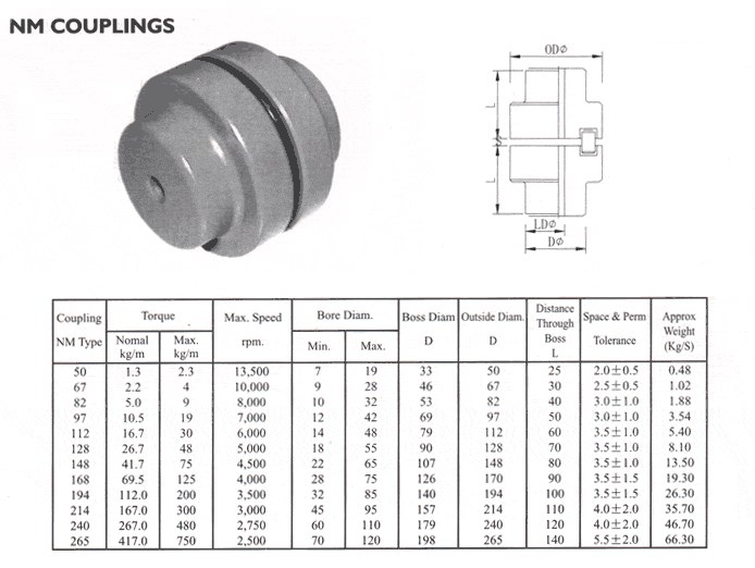
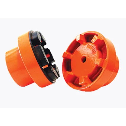
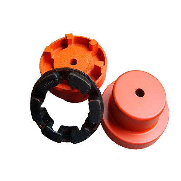
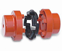
We are the leading top Chinese coupling manufacturer, and are specializing in various high quality NM coupling.
1. Material: Cast iron, Rubber. 2. OEM and ODM are available 3. High efficient in transmission 4. Finishing: Painted. 5. High quality with competitive price 6. Different models suitable for your different demands 7. Stock for different bore size on both sides available. 8. Application in wide range of environment. 9. Quick and easy mounting and disassembly. 10. Resistant to oil and electrical insulation. 11. Identical clockwise and anticlockwise rotational characteristics. 12. Small dimension, low weight, high transmitted torque. 13. It has good performance on compensating the misalignment.
Are there any safety considerations when using flexible couplings in rotating machinery?
Yes, there are several safety considerations to keep in mind when using flexible couplings in rotating machinery. While flexible couplings offer numerous benefits in terms of misalignment compensation, vibration isolation, and shock absorption, improper use or maintenance can lead to safety hazards. Here are some important safety considerations:
Proper Installation: Ensure that the flexible coupling is installed correctly and securely following the manufacturer’s guidelines. Improper installation can lead to coupling failure, unexpected disconnection, or ejection of coupling components, which may result in equipment damage or injury to personnel.
Alignment: Proper shaft alignment is essential for the reliable and safe operation of flexible couplings. Misaligned shafts can cause excessive stress on the coupling and connected components, leading to premature wear and possible failure. Regularly check and maintain proper shaft alignment to prevent safety risks.
Operating Conditions: Consider the environmental and operating conditions of the machinery when selecting a flexible coupling. Some couplings are designed for specific temperature ranges, hazardous environments, or corrosive atmospheres. Using a coupling that is not suitable for the operating conditions can compromise safety and performance.
Torque and Speed Limits: Always operate the flexible coupling within its specified torque and speed limits. Exceeding these limits can cause coupling failure, leading to unexpected downtime, equipment damage, and potential safety hazards.
Maintenance: Regularly inspect and maintain the flexible coupling to ensure its continued safe operation. Check for signs of wear, damage, or corrosion, and promptly replace any worn or damaged components with genuine parts from the manufacturer.
Emergency Stop Mechanism: In applications where safety is critical, consider implementing an emergency stop mechanism to quickly halt machinery operation in case of coupling failure or other emergencies.
Personal Protective Equipment (PPE): When working with rotating machinery or during maintenance tasks involving couplings, personnel should wear appropriate PPE, such as gloves, eye protection, and clothing that can resist entanglement hazards.
Training and Awareness: Ensure that personnel working with the machinery understand the potential hazards associated with flexible couplings and receive proper training on safe handling, installation, and maintenance procedures.
By adhering to these safety considerations, operators and maintenance personnel can mitigate potential risks and ensure the safe and reliable operation of rotating machinery with flexible couplings. Additionally, it is essential to comply with relevant safety standards and regulations specific to the industry and application to ensure a safe working environment.
What are the differences between elastomeric and metallic flexible coupling designs?
Elastomeric and metallic flexible couplings are two distinct designs used to transmit torque and accommodate misalignment in mechanical systems. Each type offers unique characteristics and advantages, making them suitable for different applications.
Elastomeric Flexible Couplings:
Elastomeric flexible couplings, also known as flexible or jaw couplings, employ an elastomeric material (rubber or similar) as the flexible element. The elastomer is typically molded between two hubs, and it acts as the connector between the driving and driven shafts. The key differences and characteristics of elastomeric couplings include:
Misalignment Compensation: Elastomeric couplings are designed to handle moderate levels of angular, parallel, and axial misalignment. The elastomeric material flexes to accommodate the misalignment while transmitting torque between the shafts.
Vibration Damping: The elastomeric material in these couplings offers excellent vibration dampening properties, reducing the transmission of vibrations from one shaft to another. This feature helps protect connected equipment from excessive vibrations and enhances system reliability.
Shock Load Absorption: Elastomeric couplings can absorb and dampen shock loads, protecting the system from sudden impacts or overloads.
Cost-Effective: Elastomeric couplings are generally more cost-effective compared to metallic couplings, making them a popular choice for various industrial applications.
Simple Design and Installation: Elastomeric couplings often have a straightforward design, allowing for easy installation and maintenance.
Lower Torque Capacity: These couplings have a lower torque capacity compared to metallic couplings, making them suitable for applications with moderate torque requirements.
Common Applications: Elastomeric couplings are commonly used in pumps, compressors, fans, conveyors, and other applications that require moderate torque transmission and misalignment compensation.
Metallic Flexible Couplings:
Metallic flexible couplings use metal components (such as steel, stainless steel, or aluminum) to connect the driving and driven shafts. The metallic designs can vary significantly depending on the type of metallic coupling, but some general characteristics include:
High Torque Capacity: Metallic couplings have higher torque transmission capabilities compared to elastomeric couplings. They are well-suited for applications requiring high torque handling.
Misalignment Compensation: Depending on the design, some metallic couplings can accommodate minimal misalignment, but they are generally not as flexible as elastomeric couplings in this regard.
Stiffer Construction: Metallic couplings are generally stiffer than elastomeric couplings, offering less vibration dampening but higher torsional stiffness.
Compact Design: Metallic couplings can have a more compact design, making them suitable for applications with limited space.
Higher Precision: Metallic couplings often offer higher precision and concentricity, resulting in better shaft alignment.
Higher Cost: Metallic couplings are typically more expensive than elastomeric couplings due to their construction and higher torque capacity.
Common Applications: Metallic couplings are commonly used in high-speed machinery, precision equipment, robotics, and applications with high torque requirements.
Summary:
In summary, the main differences between elastomeric and metallic flexible coupling designs lie in their flexibility, torque capacity, vibration dampening, cost, and applications. Elastomeric couplings are suitable for applications with moderate torque, misalignment compensation, and vibration dampening requirements. On the other hand, metallic couplings are chosen for applications with higher torque and precision requirements, where flexibility and vibration dampening are less critical.
What are the advantages of using flexible couplings in mechanical systems?
Flexible couplings offer several advantages in mechanical systems, making them essential components in various applications. Here are the key advantages of using flexible couplings:
Misalignment Compensation: One of the primary advantages of flexible couplings is their ability to compensate for shaft misalignment. In mechanical systems, misalignment can occur due to various factors such as installation errors, thermal expansion, or shaft deflection. Flexible couplings can accommodate angular, parallel, and axial misalignment, ensuring smooth power transmission and reducing stress on the connected equipment and shafts.
Vibration Damping: Flexible couplings act as damping elements, absorbing and dissipating vibrations and shocks generated during operation. This feature helps to reduce noise, protect the equipment from excessive wear, and enhance overall system reliability and performance.
Torsional Flexibility: Flexible couplings provide torsional flexibility, allowing them to handle slight angular and axial deflections. This capability protects the equipment from sudden torque fluctuations, shock loads, and torque spikes, ensuring smoother operation and preventing damage to the machinery.
Overload Protection: In case of sudden overloads or torque spikes, flexible couplings can absorb and distribute the excess torque, protecting the connected equipment and drivetrain from damage. This overload protection feature prevents unexpected failures and reduces downtime in critical applications.
Reduce Wear and Maintenance: By compensating for misalignment and damping vibrations, flexible couplings help reduce wear on the connected equipment, bearings, and seals. This results in extended component life and reduced maintenance requirements, leading to cost savings and improved system reliability.
Compensation for Thermal Expansion: In systems exposed to temperature variations, flexible couplings can compensate for thermal expansion and contraction, maintaining proper alignment and preventing binding or excessive stress on the equipment during temperature changes.
Electric Isolation: Some types of flexible couplings, such as disc couplings, offer electrical isolation between shafts. This feature is beneficial in applications where galvanic corrosion or electrical interference between connected components needs to be minimized.
Space and Weight Savings: Flexible couplings often have compact designs and low inertia, which is advantageous in applications with space constraints and where minimizing weight is crucial for performance and efficiency.
Cost-Effectiveness: Flexible couplings are generally cost-effective solutions for power transmission and motion control, especially when compared to more complex and expensive coupling types. Their relatively simple design and ease of installation contribute to cost savings.
In summary, flexible couplings play a vital role in mechanical systems by providing misalignment compensation, vibration damping, overload protection, and torsional flexibility. These advantages lead to improved system performance, reduced wear and maintenance, and enhanced equipment reliability, making flexible couplings a preferred choice in various industrial, automotive, marine, and aerospace applications.
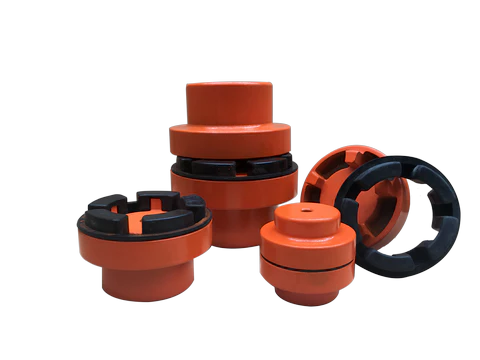
We are the leading top Chinese coupling manufacturer, and are specializing in various high quality NM coupling.
1. Material: Cast iron, Rubber. 2. OEM and ODM are available 3. High efficient in transmission 4. Finishing: Painted. 5. High quality with competitive price 6. Different models suitable for your different demands 7. Stock for different bore size on both sides available. 8. Application in wide range of environment. 9. Quick and easy mounting and disassembly. 10. Resistant to oil and electrical insulation. 11. Identical clockwise and anticlockwise rotational characteristics. 12. Small dimension, low weight, high transmitted torque. 13. It has good performance on compensating the misalignment.
How does a flexible coupling handle angular, parallel, and axial misalignment?
A flexible coupling is designed to accommodate various types of misalignment between two rotating shafts: angular misalignment, parallel misalignment, and axial misalignment. The flexibility of the coupling allows it to maintain a connection between the shafts while compensating for these misalignment types. Here’s how a flexible coupling handles each type of misalignment:
Angular Misalignment: Angular misalignment occurs when the axes of the two shafts are not collinear and form an angle with each other. Flexible couplings can handle angular misalignment by incorporating an element that can flex and bend. One common design is the “spider” or “jaw” element, which consists of elastomeric materials. As the shafts are misaligned, the elastomeric element can deform slightly, allowing the coupling to accommodate the angular offset between the shafts while still transmitting torque.
Parallel Misalignment: Parallel misalignment, also known as offset misalignment, occurs when the axes of the two shafts are parallel but not perfectly aligned with each other. Flexible couplings can handle parallel misalignment through the same elastomeric element. The flexible nature of the element enables it to shift and adjust to the offset between the shafts, ensuring continuous power transmission while minimizing additional stresses on the machinery.
Axial Misalignment: Axial misalignment, also called end-play misalignment, occurs when the two shafts move closer together or farther apart along their common axis. Flexible couplings can handle axial misalignment through specific designs that allow limited axial movement. For instance, some couplings use slotted holes or a floating member that permits axial displacement while maintaining the connection between the shafts.
By providing the capability to handle angular, parallel, and axial misalignment, flexible couplings offer several advantages for power transmission systems:
They help to prevent premature wear and damage to the connected equipment, reducing maintenance and replacement costs.
They minimize vibration and shock loads, enhancing the overall smoothness and reliability of the machinery.
They reduce the risk of equipment failure due to misalignment-induced stresses, improving the system’s operational life.
They allow for easier installation and alignment adjustments, saving time and effort during setup and maintenance.
Overall, flexible couplings play a crucial role in handling misalignment and ensuring efficient power transmission in various industrial applications.
What are the differences between elastomeric and metallic flexible coupling designs?
Elastomeric and metallic flexible couplings are two distinct designs used to transmit torque and accommodate misalignment in mechanical systems. Each type offers unique characteristics and advantages, making them suitable for different applications.
Elastomeric Flexible Couplings:
Elastomeric flexible couplings, also known as flexible or jaw couplings, employ an elastomeric material (rubber or similar) as the flexible element. The elastomer is typically molded between two hubs, and it acts as the connector between the driving and driven shafts. The key differences and characteristics of elastomeric couplings include:
Misalignment Compensation: Elastomeric couplings are designed to handle moderate levels of angular, parallel, and axial misalignment. The elastomeric material flexes to accommodate the misalignment while transmitting torque between the shafts.
Vibration Damping: The elastomeric material in these couplings offers excellent vibration dampening properties, reducing the transmission of vibrations from one shaft to another. This feature helps protect connected equipment from excessive vibrations and enhances system reliability.
Shock Load Absorption: Elastomeric couplings can absorb and dampen shock loads, protecting the system from sudden impacts or overloads.
Cost-Effective: Elastomeric couplings are generally more cost-effective compared to metallic couplings, making them a popular choice for various industrial applications.
Simple Design and Installation: Elastomeric couplings often have a straightforward design, allowing for easy installation and maintenance.
Lower Torque Capacity: These couplings have a lower torque capacity compared to metallic couplings, making them suitable for applications with moderate torque requirements.
Common Applications: Elastomeric couplings are commonly used in pumps, compressors, fans, conveyors, and other applications that require moderate torque transmission and misalignment compensation.
Metallic Flexible Couplings:
Metallic flexible couplings use metal components (such as steel, stainless steel, or aluminum) to connect the driving and driven shafts. The metallic designs can vary significantly depending on the type of metallic coupling, but some general characteristics include:
High Torque Capacity: Metallic couplings have higher torque transmission capabilities compared to elastomeric couplings. They are well-suited for applications requiring high torque handling.
Misalignment Compensation: Depending on the design, some metallic couplings can accommodate minimal misalignment, but they are generally not as flexible as elastomeric couplings in this regard.
Stiffer Construction: Metallic couplings are generally stiffer than elastomeric couplings, offering less vibration dampening but higher torsional stiffness.
Compact Design: Metallic couplings can have a more compact design, making them suitable for applications with limited space.
Higher Precision: Metallic couplings often offer higher precision and concentricity, resulting in better shaft alignment.
Higher Cost: Metallic couplings are typically more expensive than elastomeric couplings due to their construction and higher torque capacity.
Common Applications: Metallic couplings are commonly used in high-speed machinery, precision equipment, robotics, and applications with high torque requirements.
Summary:
In summary, the main differences between elastomeric and metallic flexible coupling designs lie in their flexibility, torque capacity, vibration dampening, cost, and applications. Elastomeric couplings are suitable for applications with moderate torque, misalignment compensation, and vibration dampening requirements. On the other hand, metallic couplings are chosen for applications with higher torque and precision requirements, where flexibility and vibration dampening are less critical.
What is a flexible coupling and how does it work?
A flexible coupling is a mechanical device used to connect two shafts while allowing for relative movement between them. It is designed to transmit torque from one shaft to another while compensating for misalignment, vibration, and shock. Flexible couplings are essential components in various rotating machinery and systems, as they help protect the connected equipment and enhance overall performance.
Types of Flexible Couplings:
There are several types of flexible couplings, each with its unique design and characteristics. Some common types include:
Jaw Couplings: Jaw couplings feature elastomer spiders that fit between two hubs. They can accommodate angular and parallel misalignment while dampening vibrations.
Disc Couplings: Disc couplings use thin metallic discs to connect the shafts. They are highly flexible and provide excellent misalignment compensation.
Gear Couplings: Gear couplings use gear teeth to transmit torque. They offer high torque capacity and can handle moderate misalignment.
Beam Couplings: Beam couplings use a single piece of flexible material, such as a metal beam, to transmit torque while compensating for misalignment.
Bellows Couplings: Bellows couplings use a bellows-like structure to allow for axial, angular, and parallel misalignment compensation.
Oldham Couplings: Oldham couplings use three discs, with the middle one having a perpendicular slot to allow for misalignment compensation.
How a Flexible Coupling Works:
The operation of a flexible coupling depends on its specific design, but the general principles are similar. Let’s take the example of a jaw coupling to explain how a flexible coupling works:
Two shafts are connected to the coupling hubs on either side, with an elastomer spider placed between them.
When torque is applied to one shaft, it causes the spider to compress and deform slightly, transmitting the torque to the other shaft.
In case of misalignment between the shafts, the elastomer spider flexes and compensates for the misalignment, ensuring smooth torque transmission without imposing excessive loads on the shafts or connected equipment.
The elastomer spider also acts as a damping element, absorbing vibrations and shocks during operation, which reduces wear on the equipment and enhances system stability.
Overall, the flexibility and ability to compensate for misalignment are the key features that allow a flexible coupling to function effectively. The choice of a specific flexible coupling type depends on the application’s requirements, such as torque capacity, misalignment compensation, and environmental conditions.
To take out a hydraulic cylinder end cap, stick to these common measures:
one. Safety Safety measures: Make certain that the hydraulic procedure is depressurized and observe proper security protocols, these kinds of as putting on protective gear.
2. Accessibility the Conclude Cap: Depending on the cylinder design and style, you may want to remove any protective handles, guards, or other elements that might obstruct accessibility to the conclusion cap.
3. Detect Retaining System: Hydraulic cylinder conclude caps are typically secured in position by retaining procedures these types of as bolts, screws, or threaded connections. Identify the specific retaining system employed on your cylinder.
4. Take away Retaining Bolts or Screws: If the stop cap is secured with bolts or screws, use the ideal instruments (such as a wrench or socket set) to loosen and clear away them. Make certain that you assist the end cap as you clear away the final retaining fastener to prevent it from falling.
five. Loosen Threaded Connections: If the end cap is secured with a threaded connection, use a acceptable wrench or spanner to loosen the link. Dependent on the design, you might want to apply gentle heat or penetrating oil to help loosen any stubborn connections.
6. Tap or Pry: If the close cap is stubborn and does not arrive off very easily, you can use a comfortable-confronted mallet or a rubber mallet to faucet on the conclude cap gently. This can support split any seal or corrosion that may perhaps be holding it in location. Alternatively, you can use a pry bar or a screwdriver (carefully) to utilize leverage and pry the stop cap off.
7. Eliminate the Finish Cap: After the retaining approach is undone or loosened, carefully slide or pull the conclude cap away from the cylinder barrel. Be cautious not to injury any sealing surfaces or other elements all through the removal system.
8. Examine and Clear: After eliminating the finish cap, examine the sealing surfaces, piston, rod, and other interior China hydraulic cylinders exporter components for any dress in, injury, or contamination. Clean the stop cap and interior parts making use of an suitable solvent if necessary.
It really is vital to observe that the unique steps and processes may perhaps vary dependent on the structure and company of the hydraulic cylinder. It is advisable to talk to the manufacturer’s recommendations or request support from a capable hydraulic technician when eradicating a China hydraulic cylinders exporter cylinder finish cap to be certain proper process and safety.
A China hydraulic cylinders manufacturer cylinder is a mechanical unit that converts hydraulic power into linear drive and motion. It is composed of a cylindrical barrel, a piston, a piston rod, and several seals. Here’s a simplified rationalization of how a hydraulic cylinder functions:
1. Hydraulic Fluid Provide: The hydraulic cylinder is linked to a hydraulic system that provides pressurized hydraulic fluid, ordinarily oil, to the cylinder.
two. Cylinder Barrel and Piston: The cylinder barrel is a hollow tube where by the piston moves back and forth. The piston divides the cylinder into two chambers: the rod facet (also known as the “blind” aspect) and the cap aspect.
3. Piston and Piston Rod: The piston is a cylindrical component that fits tightly within the cylinder barrel. It has sealing rings or seals all-around its circumference to reduce fluid leakage concerning the piston and the cylinder partitions. The piston rod is attached to one end of the piston and extends exterior the cylinder barrel.
4. Hydraulic Fluid Pressure: When hydraulic fluid is equipped to a single of the chambers, it creates pressure on the piston, pushing it towards the opposite close of the cylinder. The tension is created by a hydraulic pump and controlled by valves in the hydraulic program.
five. Linear Movement: As the hydraulic fluid force acts on the piston, it forces the piston and piston rod to go in a linear course. The path of the linear motion depends on which chamber is pressurized.
six. Force and Function: The hydraulic cylinder generates power in proportion to the hydraulic fluid force and the successful region of the piston. The pressure exerted by the cylinder can be calculated utilizing the components: Drive = Tension × Piston Location.
seven. Sealing: Seals or sealing rings are made use of to stop hydraulic fluid leakage concerning the piston and China hydraulic cylinders distributor cylinder barrel. These seals be certain that the hydraulic force is contained in just the cylinder, letting it to produce pressure and conduct do the job correctly.
8. Control and Route: China hydraulic cylinders exporter The circulation of hydraulic fluid to the different chambers of the cylinder is controlled by valves in the hydraulic system. These valves immediate the fluid to the ideal chamber, allowing for exact handle of the cylinder’s motion and operation.
Hydraulic cylinders are generally applied in several programs, these types of as design gear, industrial machinery, automotive units, and additional, the place linear power and movement are needed.
To measure a hydraulic cylinder, you will need to have a several basic resources these as a tape evaluate or calipers. Below are the techniques to measure a hydraulic cylinder:
1. Figure out the Duration: Measure the overall size of the cylinder by measuring from the center of a person mounting hole to the center of the reverse mounting gap. This will give you the stroke duration of the cylinder.
two. Evaluate the Bore Sizing: The bore size refers to the inner diameter of the cylinder barrel. It is important to evaluate the bore accurately as it determines the pressure and ability of the cylinder. Use calipers or a micrometer to evaluate the diameter of the cylinder bore. Ensure that you evaluate across the heart of the cylinder bore and not the worn or destroyed areas.
three. Measure the Rod Sizing: The rod dimension refers to the diameter of the piston rod. Measure the diameter of the rod using calipers or a micrometer. Once again, evaluate across the center of the rod and not any worn or damaged areas.
4. Evaluate the Rod Size: Evaluate the size of the piston rod from the middle of the piston to the conclude of the rod.
5. Examine Mounting Type: Notice the mounting design and style of the cylinder, whether it is flange-mounted, clevis-mounted, or other varieties. This information and facts is important when replacing or choosing a cylinder.
6. Check out Seal Sort: Identify the form of seals used in the cylinder, these as piston seals, rod seals, or wiper seals. This facts is critical when purchasing replacement seals.
It is essential to measure hydraulic cylinders correctly to assure good healthy and efficiency. If you are not sure or will need aid, it is recommended to consult the manufacturer’s documentation or request assist from a China hydraulic cylinders specialist to assure exact measurements and appropriate substitute.
 The most important perform of an China agricultural gearbox exporter gearbox is to modify the tempo and torque of the energy transmitted from the input provide, this variety of as a tractor’s electrical electrical power get-off (PTO) or motor, to the output shaft that drives the have out or attachment. It will enable farmers to adapt the electrical electricity and tempo specs to match the particular endeavor at hand, these as plowing, China agricultural gearbox exporter tilling, mowing, or harvesting.
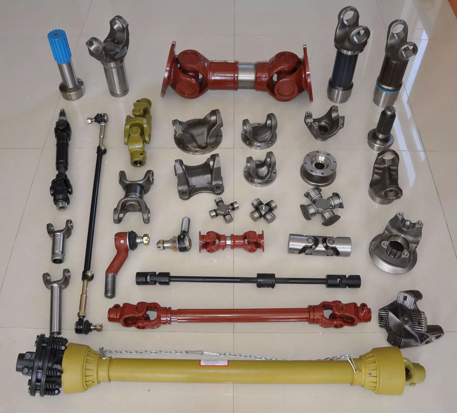 2. Harvesting Parts: Harvesting products, these kinds of as mix harvesters, necessitates pieces like cutting blades, sieves,